- Home
- :
- All Communities
- :
- Industries
- :
- Transportation
- :
- Public Transit
- :
- Public Transit Questions
- :
- I have a Polyline Feature class that I wish to mai...
- Subscribe to RSS Feed
- Mark Topic as New
- Mark Topic as Read
- Float this Topic for Current User
- Bookmark
- Subscribe
- Mute
- Printer Friendly Page
I have a Polyline Feature class that I wish to maintain in 3D Editing
- Mark as New
- Bookmark
- Subscribe
- Mute
- Subscribe to RSS Feed
- Permalink
- Report Inappropriate Content
Hi All,
I'm looking for guidance or a miracle..
I have a Polyline feature class that is Z aware when first built but to adjust and add new features to it. It seems I can only create another Feature class with the updated Z aware Polyline features. and generally having to delete and replace data in the database to maintain the static dataset.
I have tried ArcScene to edit in 3d with very limited success, ie it takes about 10 minutes to digitize a line of 15 vertices 250 metres long (display performance is slow). And then often it will not populate the Z attribute of the vertices along the line, I have only been successful once. (I have tried different Elevation Sources from Raster to TIN and a few others TIF etc).
If I restart the same session and reload the ArcScene document the next day and add a new feature it again takes 10 minutes and has lost the z awareness,
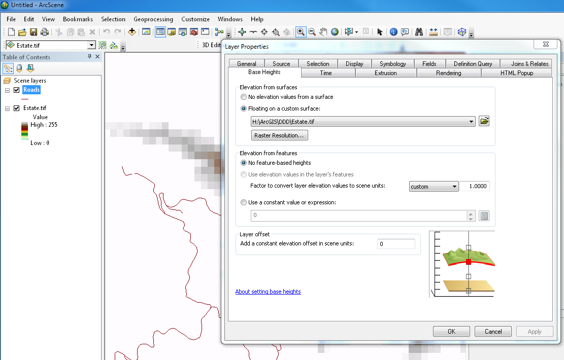
The Polyline Layer knows the Elevations are derived from the 3D Surface but it will not populate the Z value.
I would actually prefer to edit the Z aware features in ArcMap as it is linked to another relational database so if I split a polyline in half it's ID also needs to be updated in the relational database with appropriate new records added.
The 3D line itself only really needs it's Start point and Finish point Z values to be known as I am trying to calculate Gradient of the line over the surface.
To me this sounds like basic 3D editing but I am surprised that I cannot do it easily or quickly. as all I am wanting is the Z value interpolated from the surface to be stored with the Polyline itself.
Why change Polyline features you ask? Well it is all about decision processes of determining Gradient and keeping the gradient within physical constraints such as 12% slope between end points. If you shift the polyline up or down the surface in XY, the Z value has to change also, so I need to reflect this in as near as possible to real time during the editing process, whilst maintaining the links to the relational database.
I am just at a loss as to how to achieve this easily. The modifications could encompass 50 -100 alterations in any one session, and one gradient change affects the next polyline gradient in the network of line features.
Thanks
Mat Boonen , Hikurangi . NZ
Solved! Go to Solution.
Accepted Solutions
- Mark as New
- Bookmark
- Subscribe
- Mute
- Subscribe to RSS Feed
- Permalink
- Report Inappropriate Content
In case you want to use the FieldCalculator you could do this:
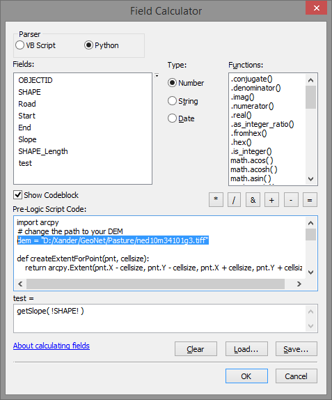
- Select Python as parser
- Activate the option "Show Codeblock"
- Paste the code below in the codeblock
- change the path to your DEM (see line 3 of the code below)
- Specify "getSlope( !SHAPE! )" to assign to your output field (in my case the field " test")
Code block:
import arcpy
# change the path to your DEM
dem = "D:/Xander/GeoNet/Pasture/ned10m34101g3.tiff"

def createExtentForPoint(pnt, cellsize):
    return arcpy.Extent(pnt.X - cellsize, pnt.Y - cellsize, pnt.X + cellsize, pnt.Y + cellsize)

def getRowColExtentFromXY(ext, pnt, cellsize):
    col = int(((pnt.X - ext.XMin) - ((pnt.X - ext.XMin) % cellsize)) / cellsize)
    row = int(((ext.YMax - pnt.Y) - ((ext.YMax - pnt.Y) % cellsize)) / cellsize)
    return row, col

def createNumpyArrayUsingExtent(raster, ext, cellsize):
    lowerLeft = arcpy.Point(ext.XMin, ext.YMin)
    ncols = int(ext.width / cellsize)
    nrows = int(ext.height / cellsize)
    return arcpy.RasterToNumPyArray(raster, lowerLeft, ncols, nrows)

def adaptExtentUsingRaster(ext, raster, cellsize):
    ras_ext = arcpy.Describe(raster).extent
    xmin = ext.XMin - ((ext.XMin - ras_ext.XMin) % cellsize)
    ymin = ext.YMin - ((ext.YMin - ras_ext.YMin) % cellsize)
    xmax = ext.XMax + ((ras_ext.XMax - ext.XMax) % cellsize)
    ymax = ext.YMax + ((ras_ext.YMax - ext.YMax) % cellsize)
    return arcpy.Extent(xmin, ymin, xmax, ymax)

def getRasterCellSize(raster):
    desc = arcpy.Describe(raster)
    return (desc.meanCellHeight + desc.meanCellWidth) / 2

def getSlope(polyline):
    cellsize = getRasterCellSize(dem)
    pnts = [polyline.firstPoint, polyline.lastPoint]
    elevs = []
    for pnt in pnts:
        ext1 = createExtentForPoint(pnt, cellsize)
        ext2 = adaptExtentUsingRaster(ext1, dem, cellsize)
        np = createNumpyArrayUsingExtent(dem, ext2, cellsize)
        row, col = getRowColExtentFromXY(ext2, pnt, cellsize)
        z = np.item(row,col)
        elevs.append(z)
    zdif = elevs[1] - elevs[0]
    slope = float(zdif / polyline.length)
    return slope
This was the result on my test set:
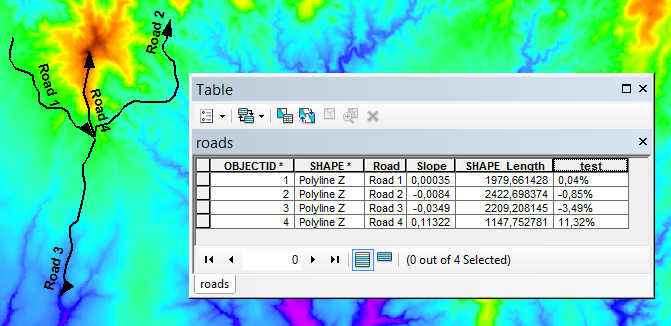
You can use the numeric format of the field to represent the calculated fraction as percentage.
- Mark as New
- Bookmark
- Subscribe
- Mute
- Subscribe to RSS Feed
- Permalink
- Report Inappropriate Content
Do you know the "Add Surface Information (3D Analyst)" tool? It will add this information to a polyline based on a surface.
For a polyline it will add:
3D distance of the line along the surface.
Minimum, maximum, and mean elevation and slope of the line along the surface.
- Mark as New
- Bookmark
- Subscribe
- Mute
- Subscribe to RSS Feed
- Permalink
- Report Inappropriate Content
Thanks Xander,
But Sadly that only finds Max and Min plus Mean Z it will not interpolate the Z at the beginning and end of the Polyline which is what i need. generally the Max and Min are not always at the start or finish of each line.
I have got a little further with using ArcScene in that if I have a very small surface model (250 hectares in size) it seems to be a lot more stable in that environment. Strictly speaking I dont even wish to render the surface model in 3d anyway . a 2D view to digitize is fine, I just want the extract Z heights as above.
I could break my surface model into hundred of tiles but that also seems a bit of a compromise. especially when trying to associate the Polyline with the correct surface model under it.
- Mark as New
- Bookmark
- Subscribe
- Mute
- Subscribe to RSS Feed
- Permalink
- Report Inappropriate Content
Personally I would be more interested in knowing the elevation difference in the entire trajectory then only at the start and end positions, especially in cases like the one below:

However, I you want to extract start and end height, determine the difference between them and divide it by the length to obtain the slope, this could be scripted with some Python code. This is much faster than editing in ArcScene in a 3D environment.
You may also want to consider editing in ArcGIS Pro (if you have access to it) since it has enhanced performance for 3D editing workflows.
Guidelines for editing features with base height properties in 3D—Help | ArcGIS for Desktop
- Mark as New
- Bookmark
- Subscribe
- Mute
- Subscribe to RSS Feed
- Permalink
- Report Inappropriate Content
I know what you mean, the truth is engineers place the line at strategic locations to minimize the possibility of creating the variance that you describe, and generally these sections represent the start and finish height of each section of road. to create an overall gradient between the two locations, the peice in the middle is just the effort amount to get to the finished requirement, but we first need to know that the gradient is not too steep overall, the balancing (or lack thereof)of cuts and fills is really the nuts and bolts of getting the grade from one point to the next right.
I have Arc Pro, but need to come up to speed with that too As 3D editing is not so obvious as yet.
I have used the Guidelines for editing features with base height properties in 3D—Help | ArcGIS for Desktop
And yet still am up against it.
- Mark as New
- Bookmark
- Subscribe
- Mute
- Subscribe to RSS Feed
- Permalink
- Report Inappropriate Content
Sounds logical what you are explaining. Maybe a field calculator script that reads out the start and end point, reads the elevation from a defined source for those points and calculates the slope between start and end point could be a solution. I will look into that and let you know what I find.
For ArcGIS Pro there is a post by David Reeves with lots of useful resources here: Introduction to ArcGIS Pro for GIS Professionals (1.1) Class Resources
- Mark as New
- Bookmark
- Subscribe
- Mute
- Subscribe to RSS Feed
- Permalink
- Report Inappropriate Content
In case you want to use the FieldCalculator you could do this:
- Select Python as parser
- Activate the option "Show Codeblock"
- Paste the code below in the codeblock
- change the path to your DEM (see line 3 of the code below)
- Specify "getSlope( !SHAPE! )" to assign to your output field (in my case the field " test")
Code block:
import arcpy
# change the path to your DEM
dem = "D:/Xander/GeoNet/Pasture/ned10m34101g3.tiff"

def createExtentForPoint(pnt, cellsize):
    return arcpy.Extent(pnt.X - cellsize, pnt.Y - cellsize, pnt.X + cellsize, pnt.Y + cellsize)

def getRowColExtentFromXY(ext, pnt, cellsize):
    col = int(((pnt.X - ext.XMin) - ((pnt.X - ext.XMin) % cellsize)) / cellsize)
    row = int(((ext.YMax - pnt.Y) - ((ext.YMax - pnt.Y) % cellsize)) / cellsize)
    return row, col

def createNumpyArrayUsingExtent(raster, ext, cellsize):
    lowerLeft = arcpy.Point(ext.XMin, ext.YMin)
    ncols = int(ext.width / cellsize)
    nrows = int(ext.height / cellsize)
    return arcpy.RasterToNumPyArray(raster, lowerLeft, ncols, nrows)

def adaptExtentUsingRaster(ext, raster, cellsize):
    ras_ext = arcpy.Describe(raster).extent
    xmin = ext.XMin - ((ext.XMin - ras_ext.XMin) % cellsize)
    ymin = ext.YMin - ((ext.YMin - ras_ext.YMin) % cellsize)
    xmax = ext.XMax + ((ras_ext.XMax - ext.XMax) % cellsize)
    ymax = ext.YMax + ((ras_ext.YMax - ext.YMax) % cellsize)
    return arcpy.Extent(xmin, ymin, xmax, ymax)

def getRasterCellSize(raster):
    desc = arcpy.Describe(raster)
    return (desc.meanCellHeight + desc.meanCellWidth) / 2

def getSlope(polyline):
    cellsize = getRasterCellSize(dem)
    pnts = [polyline.firstPoint, polyline.lastPoint]
    elevs = []
    for pnt in pnts:
        ext1 = createExtentForPoint(pnt, cellsize)
        ext2 = adaptExtentUsingRaster(ext1, dem, cellsize)
        np = createNumpyArrayUsingExtent(dem, ext2, cellsize)
        row, col = getRowColExtentFromXY(ext2, pnt, cellsize)
        z = np.item(row,col)
        elevs.append(z)
    zdif = elevs[1] - elevs[0]
    slope = float(zdif / polyline.length)
    return slope
This was the result on my test set:
You can use the numeric format of the field to represent the calculated fraction as percentage.
- Mark as New
- Bookmark
- Subscribe
- Mute
- Subscribe to RSS Feed
- Permalink
- Report Inappropriate Content
Great Stuff @Xander Bakker
I must get into the nut and bolts of geometry using Python myself, it will save me plenty of heartache.
Populating the 18000 records the first time took a bit but looks to be plain sailing running the code on small subsets. as will be the case hourly from now on. So for that, awesome effort.
I was also thinking if I should differentiate between up and down slope (-/+ ve) gradients mainly because I just am lazy and don't want to make a symbol set with both negative and positive values that looks the same color range in both directions.
I might also just populate the Z values of the start and finish point plus (maybe) consider the 3d Length of the line between the start and finish point as it may impact the overall gradient a little . I am not sure reading what you have done thinks in a 3d sense or planimetric sense for the distance between start and finish points.
I also may need to do some error trapping if the polyline falls outside the extent of the DEM. (No such thing as a perfect world especially if it is displayed as incomplete data as is the case here for me.).
- Mark as New
- Bookmark
- Subscribe
- Mute
- Subscribe to RSS Feed
- Permalink
- Report Inappropriate Content
Hi, I'm glad it works for you. You are right, there is no error checking at all in the code I provided.
The slope is calculated by dividing the height difference (end elevation - start elevation) by the length (2D) of the polyline. If you would use the 3D length of the polyline, this would affect the slope in a incorrect way.
For the symbology you can also add another column and calculate the absolute slope and use that for symbology to avoid creating two ranges up- and downhill unless you want to use the symbology to distinguish between up- and downhill.
- Mark as New
- Bookmark
- Subscribe
- Mute
- Subscribe to RSS Feed
- Permalink
- Report Inappropriate Content
Yes Thanks Again Xander Bakker
I realise the 3D length will not provide the "right" result but the difference in altitude of the first point vs. the last point in each segment will have a true length between them i.e. not in a flat 2D sense length. I was thinking of just applying basic trig as follows: (But only If I can be sure that the Z has not been accounted for already in this way?)
i.e.
A²+ B² = √C
or
(zdif * zdif ) + (polyline.length * polyline.length) = (Squareroot 3dlength)
Re your Absolute Slope, Thats a great approach, I was going to take the easy way, Reselect all Gradient less than zero and then multiply selected values by negative 1 
And as for the lines outside of the DEM I have a similar selection process as above... I have a bounding polygon extent of the DEM, so I perform a select by location of Road features that are completely contained by the bounding polygons, then only perform the calculation on those records...